Improved Helical Antenna Design for 802.11b WLAN
By: PA0HOO
October the 17th 2002
To slow? Try these mirrors: 1) Dutch mirror 2) qsl
N.B: (Click here to jump to the improved PVC helix design)
Preface
The weekend of October
the 17th 2002 we tried to set up an 802.11b
WLAN radio link over just 200m.
This web page tells about our experiences, the problems and, the solution.
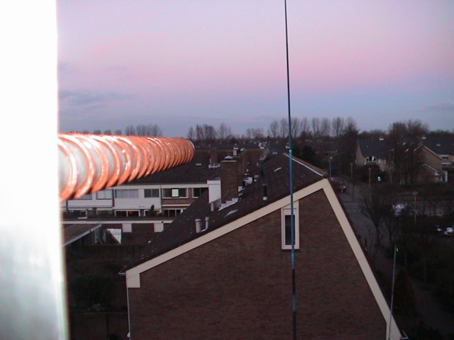
The radio path
'Direct sight', seen from the roof. See pictures below.
As we had to bridge about 200 m, an external antenna was a must.
Making your own path calculation
Click here to calculate the distance you can bridge with a given antenna.
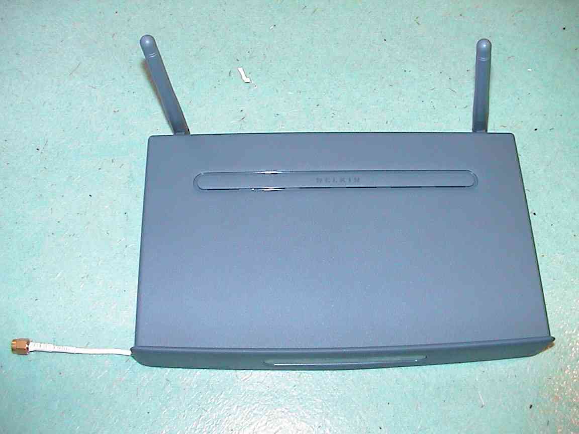
The connections for the external antennas
These pictures show how the external antenna connections were made. We used cheap surplus cables with SMA connectors. (about € 1 each).
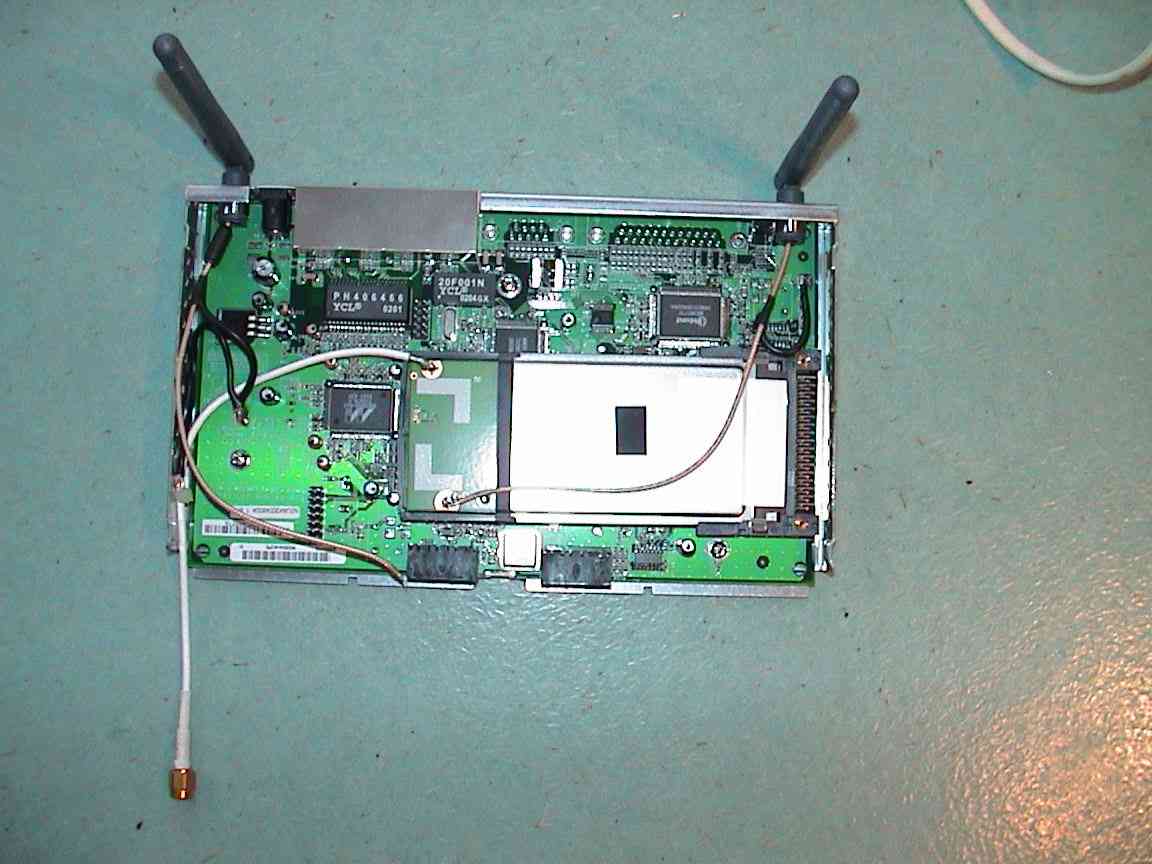
Our experience: PTFE cables don't melt while soldering.
Two antennas on at the Access Point.? This is no problem because just one antenna
is used for sending/receiving. The 'other' one is receiving only and is used for
diversity reception (getting the best out of two signals by polling both
antennas) receptions. The receiving only antenna can be kept connected as it is.
'The Antenna'
At the site of Remco PA3FYM we
found the perfect construction description of a classical helix antenna, using
today's materials. Easy to copy, cheap and non critical. We decided to build two
of those antennas.
The Disappointment
It was very disappointing to find out that 'the thingy' we made wasn't
performing at all. Even the relatively small distance of 200 m could not be
bridged. What was it that we did wrong??.
The dimension were OK, all sizes were according to the known formulas. The proven calculating programs such as helix_20 from Holger Granholm and ‘HelixCalc’ from Jason Hecker gave similar dimensions.
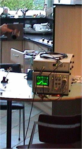
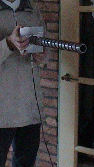
The Experiment
We tried to find out the real 'over the ether' behavior of the antennas over
a wide spectrum. We could use a cable TV spectrum analyzer up to 4 GHz and
tracking generator up to 2450 MHz. Test area: our living room...
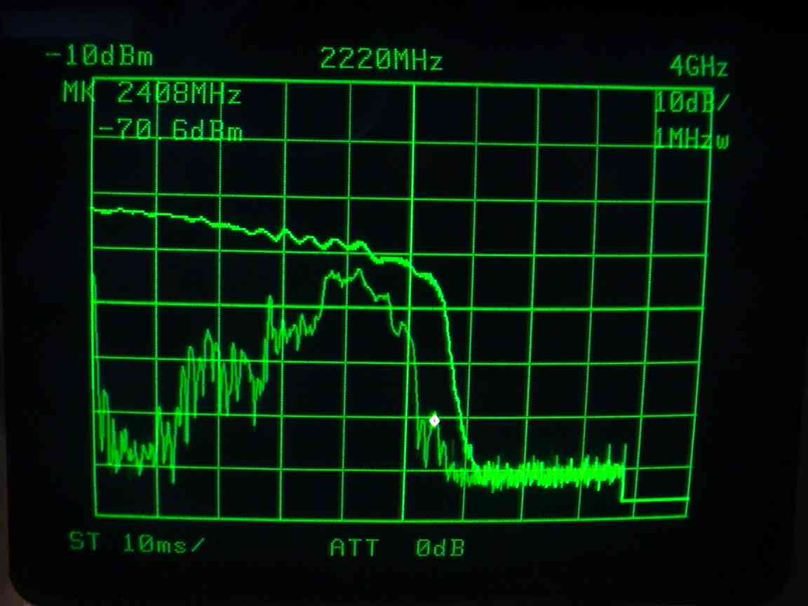
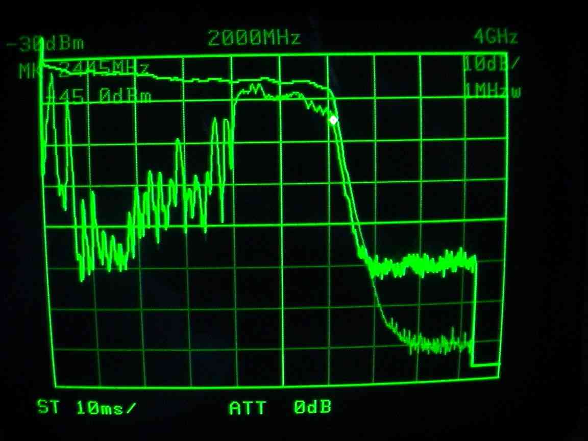
We were astonished to discover that
the antennas were radiating very well around 1650 MHz. 2450 was just outside the
band pass. See the 'test set up' and the graph below.
Detailed examination of the antenna design
Looking into detail, there IS a difference between de ordinary Helix antenna and the PVC-one: The classical helix is al 'on air' spiral, our spiral is 'on PVC'. Kraus' formulas, calculate air spirals. As our spiral is on PVC, it COULD be that the traveling velocity of the radio waves inside the antenna is being influenced because of the high εr of PVC. (similar to the cause of shortening factor of coax cables). In that case Klaus' formulas will give erroneous results.
The main question is, could our PVC plumber tube actually cause the working frequency being decreased? If the answer is 'yes', it must be possible to improve the design.
Note: for our antenna, the factor between design and reality is: 1650/2430 = 0.67
Study books say that the traveling velocity is reversed proportional with the square root of the dielectric constant.
some common values for εr:
Polyethylene: εr
= 2,25; the shortening factor is: 1/√2,25 =
0,666 (‘de coax factor’)
PVC: εr
= 4,5; the shortening factor is: 1/√4,5 =
0,47
Plexiglas: εr = 3-3,5,
the shortening factor is: 1/√3,25 = 0,55
It
appears that PVC has a fairly high dielectric constant.
As the EM field is concentrated within the spiral, were the PVC is, the
high εr
of the PVC core will influence the traveling speed for at least noticeable
factor. The local EM-field will partly go through
the air. We assume that the resulting shortening
factor will be a value somewhere in between the two extremes 0,55 and 1. The
factor 0,67 we found, 'feels' plausible.
'The proof of the pudding is in the eating'
So, we decided to design, build and test a similar downscaled Helix, designed for a 33% higher frequency.
The design
2430 MHz is about 67% of 3620 MHz. So 3620 MHz will be the design frequency of our new downscaled test antenna
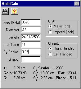 |
‘HelixCalc’
indicates that the original spiral of 42 mm is too large. We took
another standard PVC drain tube of 32 mm, the diameter of the spiral
will be 34 because of the extra PVC insulation on the wire itself.
The distance between the windings is: Sλ = 2,88 cm. |
We will keep the reflector
according the original design of Remco, 14 cm square.
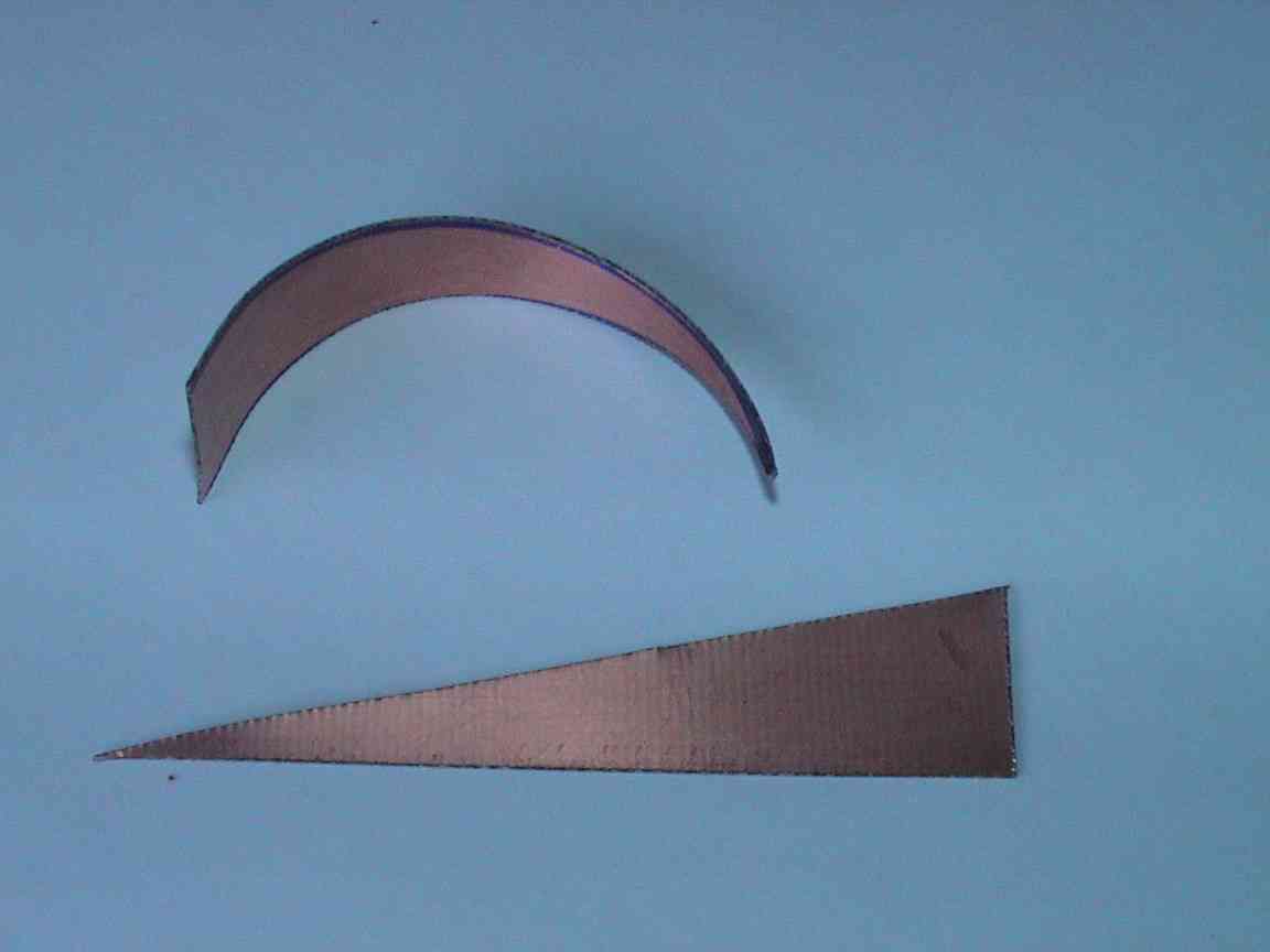
The ‘wonder’-stub from Jason Hecker will be kept as it is. See below. The original track of the spiraled wire must be followed. See Remco's site; Remco has made some nice pictures.

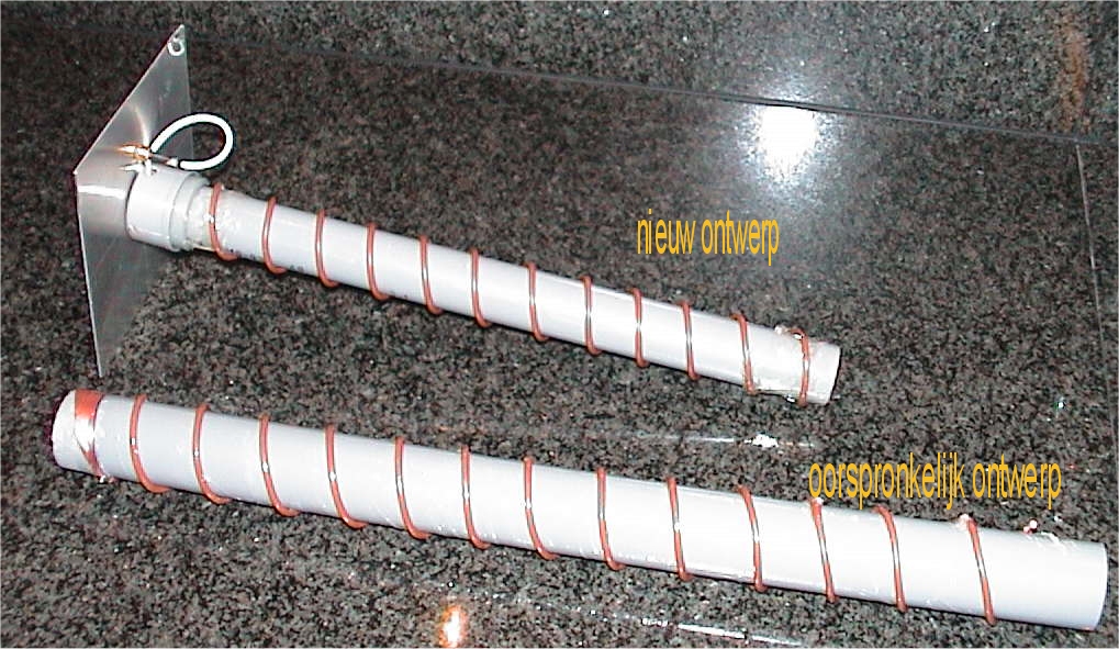
The making
We converted the old
design to the new design with smaller dimensions. See and click the picture
below
The test
In our living room, we tested again the 'ether transfer characteristic' at the distance of 5 meters.
The difference between the two antenna designs is obvious, despite of the upper limit of 2450 MHz of our equipment. The upper line is the plain directly connected coaxial antenna cable. The lower line is the antenna transfer characteristic, using the same coax, now connected to the antennas. The gain is multiplied by +30 dB. Note the markers' position and see the difference. (Both graph differ 20 dB because I forgot to make the scale of both graphs identical)
At the moment we do not have access to the right SWR measuring equipment, so proper SWR information is not available yet. If somebody took some SWR or reflected power measurements, please let me know.
Update: (June 2008): Mark Brasse describes the construction of a similar PVC - helical antenna, based on the design of Jason and using the ‘shortened’ design as per our experiences. Instead of Jason’s ‘wonder sub’ he uses a small 1/2 λ strip which can be tuned. The final results are amazing! See: ( http://www.safe-pc.net/helical.html ).
'The Eating'
The radio link, that appeared not being possible with the original design, is working very well now, using the new downscaled antenna.
A final word: In literature, a ''dielectric loaded antenna' is well known phenomena. Actually, our helical a sort of 'partly dielectric loaded helix'. (Literature example)
Once we have finished our final antenna we will put some pictures on this web page. (We're making a neat 22-turns helix now)
The final 22 -turns helix antenna (added November 30, 2002)
Below you'll find the description of a
22-turns helix antenna according to the downscaled design.
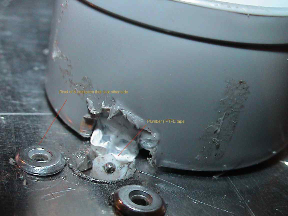
Both sides of the reflector have edges with a V-shaped cut. This is to mount the
antenna easily to the mast, using a simple clamp. The V-cut must be beside the center
line of the reflector to prevent for the antenna mast obstructing the N
connector area.
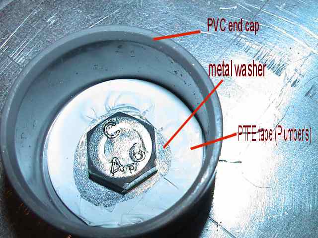
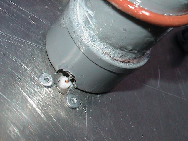
Use a 32 mm end cap. (No 40 to 32 mm converter). We used just one M8-bolt and a large washer. To prevent for electrical contact between washer and vane, we isolated the vane with two layers of PTFE tape. See picture. The dimensions of the helix spiral are: wound on a 32 mm op PVC tube, windings are spaced 2,88 cm. We used ordinary 'home installation' PVC isolated copper wire of 2,5 mm2. You can use the print out of helixcalc, but inputs have to as described above (the 'false' 3520 MHz, 3,4 cm diameter).
The vane's dimensions are
identical to the original design of Jason. (71 mm) New:
Wim Pa0wkm made the vane slightly longer This should give much better results on
SWR. No further details, however.
The vane covers more than
half the diameter of the tube. We had to cut a small piece from the end cap in
order to solder the vane to the wire.
First check if all soldering connections (no short cuts) and, if possible, do a
performance test. If everything is found to be OK, cover all soldering points
and holes with two 'slow drying' components glue. The antenna a must be
watertight, as water is absorbing very, very much at these
frequencies.
We compared the antenna
transfer characteristics of the 11-turns and the 22-turns helical antenna
(two antenna pairs). The spectrogram shows a gain difference of about 8 dB. That
is for 2 antennas, so for one antenna the gain difference is 4 dB. We found that
the thin white PTFE cable that we used with the 11-turns antenna has a
loss of almost 1 dB. This implies that the real gain difference between the
11-turns and the 22-turns antennas about 3 dB, and that is exactly according to
theory. Our 'dielectric load' downscaling approach appeared to be reproducible.
The spectrogram shows that the Helix antenna is very wide band.
(Pleas not that our signal generator really stops at 2450 MHz, we were working
in the edge. At the moment we really do NOT know how the antenna behaves above
this frequency.)
Our final 22-turns helical has a N-connector mounted at the reflector.
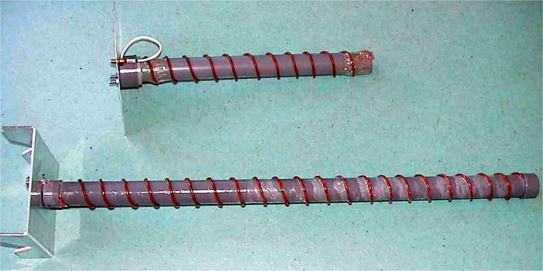 11-turns & 21-turns |
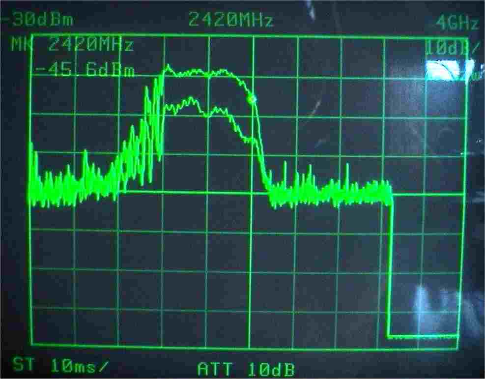 Comparation transfer between 11-turns and 22-turns |
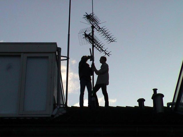 The end of the day |
.JPG) The end of the day(2) |
 helix in the mast |
 Pointig towards the target |
Some points of interest
Using the antenna for a free sight
'point to point' connection:
Optimal results will be obtained using a Helical antenna at both sides. Both
antennas must be wound in THE SAME direction. Opposite wound antennas won't
connect at all.
Sensibility to reflections
Rotating radio waves are reversed in rotating direction after
reflection by buildings etc. The Helix antenna's sensitivity is low for reverse rotating
fields. This means that a helix antenna is very good in suppressing the
effects of reflections. As WLAN is sensitive for delay spread that could
be cause by reflections, a helix antenna is the best choice for moderate point
to point connections.
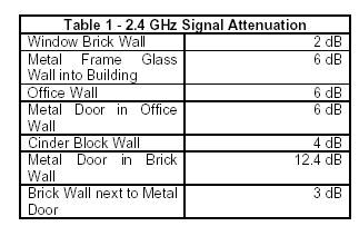
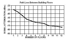
Through walls and floors
Attenuation is roughly estimated to 6 dB through ordinary walls;
concrete floors do 10 tot 30 dB. You will soon be 'out of range' between
building floors.
Using the antenna for reflected 'point to point' connection
In the case a reflecting radio path is used (such as reflecting the radio signal
to a large building to get around an path obstruction, like a mirror, use antennas that are
wound opposite.
Using the antenna with a Yagi-antenne at the other side.
This is possible. Antenna gain will be 3 dB less. Polarization of the yagi is
not critical. Winding direction of the helix spiral is not critical.
Using the antenna with an omni directional antenna at the other side.
This is possible. Antenna gain will be 3 dB less. Polarization of omni
directional antenna is not critical.
Overview of frequency of Wlan channels.
| Cannel | US/Canada | Europe | France | Espagne | Nippon |
| 1 | 2412 | 2412 | - | - | 2412 |
| 2 | 2417 | 2417 | - | - | 2417 |
| 3 | 2422 | 2422 | - | - | 2422 |
| 4 | 2427 | 2427 | - | - | 2427 |
| 5 | 2432 | 2432 | - | - | 2432 |
| 6 | 2437 | 2437 | - | - | 2437 |
| 7 | 2442 | 2442 | - | - | 2442 |
| 8 | 2447 | 2447 | - | - | 2447 |
| 9 | 2452 | 2452 | - | - | 2452 |
| 10 | 2457 | 2457 | 2457 | 2457 | 2457 |
| 11 | 2462 | 2462 | 2462 | 2462 | 2462 |
| 12 | - | 2467 | 2467 | - | 2467 |
| 13 | - | 2472 | 2472 | - | 2472 |
| 14 | - | - | - | - | 2484 |
How we connected the WLAN equipment to the antennas.
As our radio path was very short, there was no need to optimize for lowest RF losses at relative high cost.
We got from the surplus of a large project a length of IEEE 802.3 network cable of which we measured the RF losses. The losses were about 0,3 dB per meter at 2400 MHz. As a reference, good RF cable (e.g. aircomplus) is about 0,2 dB per meter. At a cable length of 5 meters, (that was all we needed), the extra losses were 0,5 dB. As we had to bridge just 200 meters, and our antenna was having a relative high gain, we decided to use this cheap (to us) network cable.
At one side we
used a SMA and N pigtail, the other side had a solid SMA to N converter. As a
general rule, prevent using pigtails, as they are expensive and generally
introduce relatively high losses. (As an example, our 30 cm pigtail had a loss of 1,5
dB, that is equivalent to 5 to 7 meter good quality RF cable). Use 'solid' converters
instead, if available.
If any remarks, you could contact me here.
Dutch
wlan links:
pioniers: www.wirelessleiden.nl
forum: www.wirelessnederland.nl
portal: portal.wirelessnederland.nl
73, pa0hoo (pa0hoo(deletethis)@qsl.net)